8 Oct 2016
I love my Minx Air 100 and I used it all the time.
Recently I have to open up the Minx Air 100 to make a minor modification so I am sharing how you can go about opening up the Minx Air 100.
Step 1 - Take off the speakers grill. The grill is held in place by 8 posts - 4 on top edge and 4 on bottom edge. Because the corner posts have silicone glue, you will find it easiest to start prying open the grill from either the centre top or centre bottom and then slowly work your way towards the corner post. Then just take your time to pry the corner posts open bit by bit. One of those blue plastic iphone prying tool works great.
Step 2 - Once the grill is taken off. It will expose the speakers and you can then unscrew the 10 Allen screws and 2 Phillip screws that held down the speakers cover.
Step 3 - you can then slowly take off the speakers cover but there are still 4 cables linking the speakers cover to the printed circuit board. 2 of these are ribbon cables for the control buttons. and the other 2 are for the speakers and the IR remote receiver. Disconnect all the cables. Hint - the ribbon cables have the contacts facing up and you need to pull the brown clips forward on both sides to release the cable.
The reason I wanted to take apart my Minx Air is that I found it really hard to tell if the unit is ON or OFF. There is power indicator on top of the unit but I could not see them where I have placed the unit. So sometimes I keep hitting the remote ON/OFF button without knowing if it is ON or OFF!!!!
Luckily adding a power LED is simple matter.
Cambridge Audio has made it fairly easy as the connector jack out of the power board is labelled as below.
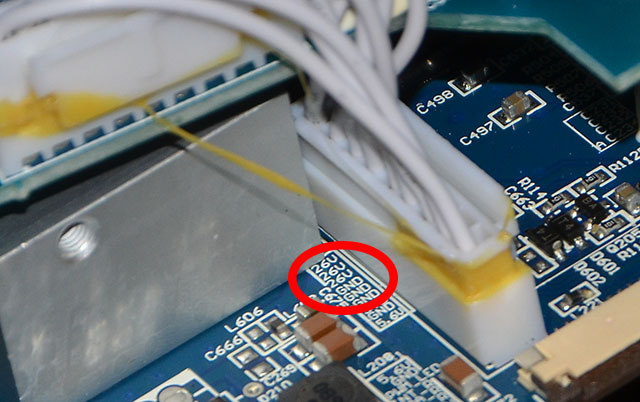
There are 2 Voltages output on the connector - 5.6V and 26V. The 5.6V is always on to power the remote control cirucuitry and the 26V is to supply the main circuit when power is ON.
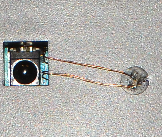
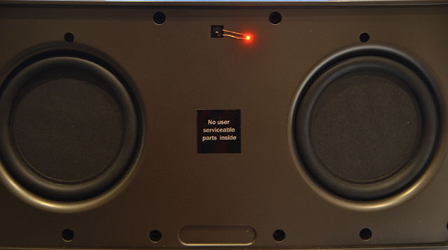
I thought that the best place to put the LED would be behind the speakers grill. So I channel a couple of thin enamel coated wire through the IR LED opening as seen in the following photo. I just glue the tiny SMD LED onto the front of the speakers assembly. Be careful where you route the wire to avoid short circuiting - use electrical tape where it is appropriate.
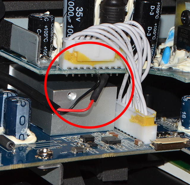
Then all you need to do is to solder a cable from the enamel wires to the power connector as below.
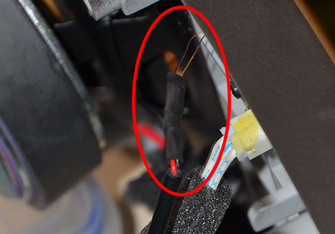
There is also a 4K7 resistor hiding inside the black heatshrink in the picture below so that the LED would receive the right current from the 26V input.
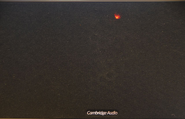
Reassemble everything in reverse order and there you have it. A Power LED that you can see!!!
©2016 - Thomas Zih. All Rights Reserved